PHOBOS GERMANIUM FUZZ 1
PROJECT NAME
PHOBOS
BASED ON
EFFECT TYPE
PROJECT SUMMARY
DOCUMENT VERSION
Tone Bender Mk. III (3-knob)
A reproduction of the third version of the Tone Bender germanium fuzz sold by Macaris in London in the
late 1960s.
Germanium fuzz 1.0.2 (2024-08-08)
BUILD DIFFICULTY
Easy
Actual size is 2.3” x 1.86” (main board) and 2.3” x 0.86” (bypass board).
This documentation is for the PCB-only version of the project. If you are building the full kit from
Aion FX, please use the kit build documentation instead. The instructions are more detailed and
may differ in some areas due to the specialized parts and assembly methods used in our kits.
IMPORTANT NOTE

PHOBOS GERMANIUM FUZZ 2
TABLE OF CONTENTS
1 Project Overview 8 Drill Template
2 Introduction & Usage 9 Enclosure Layout
3-4 Parts List 10 Wiring Diagram
5-6 Build Notes 11 Licensing
7 Schematic 11 Document Revisions
INTRODUCTION
The Phobos Germanium Fuzz is a clone of the Colorsound / Sola Sound Tone Bender Mk III. While the
first version was essentially the same topology as a Fuzz Face, and the second version added a gain stage
in front, this third version from 1967-1968 was a completely different circuit, using a Darlington-pair
transistor configuration to drive a third transistor, followed by a tone control which the earlier versions
were missing.
While the Mk. III Tone Bender was itself a variation of the Baldwin-Burns Buzzaround, it had a few
variants of its own, both official and unofficial. The Vox Tone Bender was a licensed variant with a
few parts substitutions. The Park Fuzz Sound by Park Amplification (Jim Marshall’s side-brand) was a
contemporary clone. The Elka Dizzytone and the Prescription Electronics Yard Box were two others.
Aside from the Buzzaround, all of the rest of these variations can be build on this PCB.
A note about the name: the original Colorsound / Sola Sound unit was not called the “Mark III”, but the
Vox-licensed version was. As a result, this circuit is commonly called both the “Mark III” and the “three-
knob” Tone Bender. This project will refer to it as the Mk III to differentiate it from the Mk II, which is
available as another project called the Deimos.
The Phobos project has a voltage inverter which allows you to power the effect with a standard center-
negative adapter while maintaining the positive-ground operation of the original. The PCB also includes
biasing trim pots so you can dial in a perfect bias without having to swap out resistors.
USAGE
The Phobos has three controls:
• Fuzz controls the amount of gain from the input stage that is sent to the third transistor where the
clipping occurs.
• Tone pans between two filters, with a treble emphasis on to the left and a bass emphasis to the right.
• Volume is the output volume of the effect.

PHOBOS GERMANIUM FUZZ 3
PARTS LIST
This parts list is also available in a spreadsheet format which can be imported directly into Mouser for
easy parts ordering. Mouser doesn’t carry all the parts—notably potentiometers—so the second tab lists
all the non-Mouser parts as well as sources for each.
View parts list spreadsheet →
PART VALUE TYPE NOTES
R1 47k Metal film resistor, 1/4W
R2 220k Metal film resistor, 1/4W
R3 1k Metal film resistor, 1/4W
R4 10k Metal film resistor, 1/4W
R5 3k3 Metal film resistor, 1/4W
R6 18k Metal film resistor, 1/4W
R7 1k Metal film resistor, 1/4W
R8 10k Metal film resistor, 1/4W
R9 10k Metal film resistor, 1/4W
R10 220k Metal film resistor, 1/4W
RPD 1M Metal film resistor, 1/4W Input pulldown resistor. Can be as low as 1M.
LEDR 10k Metal film resistor, 1/4W LED current-limiting resistor. Adjust value to change LED brightness.
C1 100n Film capacitor, 7.2 x 2.5mm
C2 220pF MLCC capacitor, NP0/C0G
C3 220n Film capacitor, 7.2 x 2.5mm
C4 10uF Electrolytic capacitor, 5mm
C5 100n Film capacitor, 7.2 x 2.5mm
C6 2n2 Film capacitor, 7.2 x 2.5mm
C7 100uF Electrolytic capacitor, 6.3mm
C8 10uF Electrolytic capacitor, 5mm
C9 47uF Electrolytic capacitor, 5mm
C10 470n MLCC capacitor, X7R
C11 100n MLCC capacitor, X7R
Z1 1N4742A Zener diode, 12V, DO-41
D1 1N5817 Schottky diode, DO-41
D2 Germanium Germanium diode, DO-07 Original uses 1N270, but part number isn’t important. Just use any NOS
germanium diode.

PHOBOS GERMANIUM FUZZ 4
PARTS LIST, CONT.
PART VALUE TYPE NOTES
Q1 Germanium Germanium transistor, PNP Recommended to buy a selected Tone Bender Mk III set. See build notes.
Q1-S TO-5 socket Transistor socket, TO-5
Q2 Germanium Germanium transistor, PNP Recommended to buy a selected Tone Bender Mk III set. See build notes.
Q2-S TO-5 socket Transistor socket, TO-5
Q3 Germanium Germanium transistor, PNP Recommended to buy a selected Tone Bender Mk III set. See build notes.
Q3-S TO-5 socket Transistor socket, TO-5
IC1 TC1044SCPA Voltage inverter, DIP8
IC1-S DIP-8 socket IC socket, DIP-8
Q1-2B 50k trimmer Trimmer, 10%, 1/4" Bias trimmer for Q1 and Q2. See build notes.
Q3B 50k trimmer Trimmer, 10%, 1/4" Bias trimmer for Q3. See build notes.
FUZZ 100kB 16mm right-angle PCB mount pot
TONE 100kB 16mm right-angle PCB mount pot
LEVEL 100kA 16mm right-angle PCB mount pot
LED 5mm LED, 5mm, red diffused
IN 1/4" stereo 1/4" phone jack, closed frame Switchcraft 112BX or equivalent.
OUT 1/4" mono 1/4" phone jack, closed frame Switchcraft 111X or equivalent.
DC 2.1mm DC jack, 2.1mm panel mount Mouser 163-4302-E or equivalent.
BATT Battery snap 9V battery snap Optional. Use the soft plastic type—the hard-shell type will not fit.
FSW 3PDT Stomp switch, 3PDT
ENC 125B Enclosure, die-cast aluminum Can also use a Hammond 1590N1.

PHOBOS GERMANIUM FUZZ 5
BUILD NOTES
Transistor notes
For this circuit, as with many other vintage fuzzes, it’s not so much the part number of the germanium
transistor as it is the properties—specifically, gain (hFE) and leakage.
The Tone Bender Mk III is less finicky about transistors than the Mk II, but still moreso than other
germanium circuits like the Fuzz Face or Rangemaster. You can save a lot of time by just buying a
matched set from Small Bear Electronics or eBay. However, if you don’t have access to pre-matched
transistors or you just want to source your own, here’s what to look for.
Characteristics
This is just a general guideline. There may be some transistors that meet these characteristics that won’t
sound right, and others that are outside this nominal range that will work just fine.
• Q1: hFE 50-100, low leakage (<100μA)
• Q2: hFE 50-100, low leakage (<100μA)
• Q3: hFE 90-120, medium leakage (100-300μA)
The characteristics of Q1 and Q2 are less important than Q3 due to their Darlington configuration. In
fact, many people have even used low-gain silicons for Q1/2 with no reported change in tone, since this
stage just boosts the signal and all the actual fuzz comes from overloading Q3.
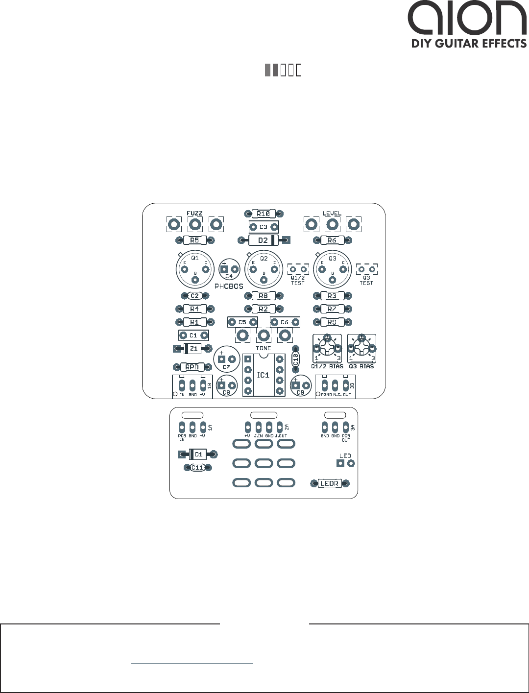
Biasing
As a starting point, set the two bias trimmers to around 9:00 (approximately 10k total resistance when
combined with R3 and R7). Then, with a multimeter, touch the black and red leads to the pads marked
“Q1/2 TEST”, which is the shared collector of Q1/2. Rotate the trimmer until the multimeter reads -3.5V.
This voltage may be positive if the test leads are reversed, but what’s important is the absolute value.
Next, touch the multimeter leads to the pads marked “Q3 TEST”. This is equivalent to the collector of
Q3. Turn the trimmer until you read -3V.
Then, turn the Tone and Fuzz controls up all the way, and turn Level up to a reasonable volume. Adjust
Q3 between -2V and -4V listening for the amount of low end, and stop when the maximum amount of
bass is to your liking—keeping in mind that the tone control also cuts bass even further when turned
down. Lower voltages (i.e. more negative) will give more low-end fullness, but the Mk. III usually sounds
best when the bass is cut back slightly.
Then, with the black lead touching ground, touch each leg of each of the transistors and see how they
line up with these target voltages.
• Q1: Collector -3.5V, Base -1.5V, Emitter -1.4V
• Q2: Collector -3.5V, Base -1.5V, Emitter -1.4V
• Q3: Collector -2V to -4V, Base -0.05V, Emitter 0V
The collector voltages are just a baseline. For Q1/2, anything from 3V to 7V will work fine and will sound
roughly the same. For Q3, the EQ does change a bit depending on the bias, but as long as the transistors
have the right characteristics, the overall character of the fuzz will be the same across the range.

PHOBOS GERMANIUM FUZZ 6
BUILD NOTES, CONT.
Variants
There were a number of other variants of Mk III that each had minor changes. Start with the original
Sola Sound Tone Bender parts list on page 3-4 of this documentation and make the following changes.
Vox Tone Bender Mk III
• R1: 100k
• R2: 680k
• C4: 6.4uF (nearest standard value today is 6.8uF)
• C6: 2n (doesn’t make much of a difference; just use 2n2 here like the Sola Sound version)
This is also identical to the Park Fuzz Sound (3-knob version), except the Park uses 2n2 for C6.
Park Fuzz Sound (2-knob)
• R1: 100k
• R2: 680k
• R10: 470k
• C2: 200pF
• C4: 25uF (nearest standard value today is 22uF)
The 2-knob version omits the Fuzz control and hardwires it full-on all the time. If you’re building this
variant, it’s recommended to keep the Fuzz control in place. If it’s turned all the way up, the unit is stock,
but this way you still have the option to turn it down.
Prescription Electronics Yard Box
• C4: 4.7uF
• Fuzz: 250kB
The Yard Box also changes R10 from a 220k fixed resistor to a 250kB pot. Most people do not find this
to be very useful since it essentially just increases the maximum volume, acting as a secondary volume
control rather than causing any major tonal changes. It’s recommended to instead use the output
volume mod in the next section.
Output volume
The 220k resistor before the volume control (R10) reduces the maximum available output volume.
While the circuit isn’t lacking in available volume, if you’d like to get a little more out of it, you can
reduce this resistor to 68k and then increase the volume control to 250kA. This gives you the same
total resistance (~320k) so the tone and output impedance is unaffected, but available output volume is
increased.
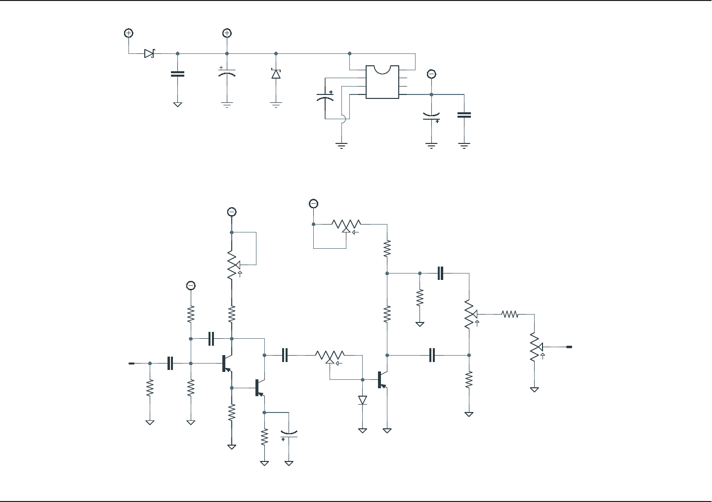
SCHEMATIC
PHOBOS GERMANIUM FUZZ 7
GND
2M2
1N5817
100uF
100kA
100kB
+9V
PWR_GND
100n
VA
47k
Ge
10k
220n
1N4742
TC1044SCPA10uF
PWR_GND PWR_GND
47uF
-VA
PWR_GND
GND
Ge
1k
-VA
Ge
18k 1k
10k
2n2
GND
GND
50kB
50kB
10k
470n
100n
GND
220k
220pF
-VA
3k3
10uF
GND GND
Ge
GND
-VA
100kB
GND
100n
GND
220k
IN
OUT
RPD
D1
C7
LEVEL
1
2
3
FUZZ
1
2
3
C11
R1
Q1
R4
C3
Z1
1
2
3
4 5
6
7
8
IC1
C8
C9
Q2
R3
Q3
R6 R7
R8
C6
Q1-2 BIAS
1
2
3
Q3 BIAS
1
2
3
R9
C10
C1
R2
C2
R5
C4
D2
TONE
1
2
3
C5
R10
GND
PHOBOS GERMANIUM FUZZ 8
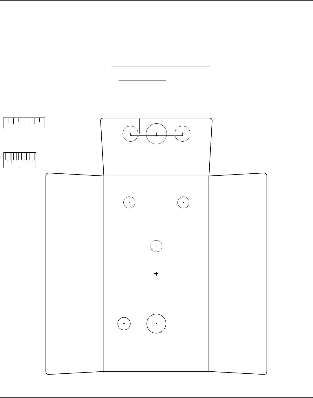
DRILL TEMPLATE
Cut out this drill template, fold the edges and tape it to the enclosure. Before drilling, it’s recommended
to first use a center punch for each of the holes to help guide the drill bit.
Ensure that this template is printed at 100% or “Actual Size”. You can double-check this by measuring
the scale on the printed page.
Top jack layout assumes the use of closed-frame jacks like the Switchcraft 111X. If you’d rather use
open-frame jacks, please refer to the Open-Frame Jack Drill Template for the top side.
LED hole drill size assumes the use of a 5mm LED bezel, available from several parts suppliers. Adjust
size accordingly if using something different, such as a 3mm bezel, a plastic bezel, or just a plain LED.
0 1 2
CM
0 1
INCH
x: -0.65, y: +1.71 x: 0.65, y: +1.71
ø9/32” ø9/32”
x: 0, y: +0.66
ø9/32”
x: 0, y: -1.20
ø15/32”
x: -0.775, y: -1.20
ø5/16”
CENTER (0,0)
ø3/8”
ø1/2”
0.385”
0.625” 0.625”
ø3/8”
OUT
DC
IN
125B
VOLUME
TONE
FUZZ
FOOTSWITCHLED
PHOBOS GERMANIUM FUZZ 9
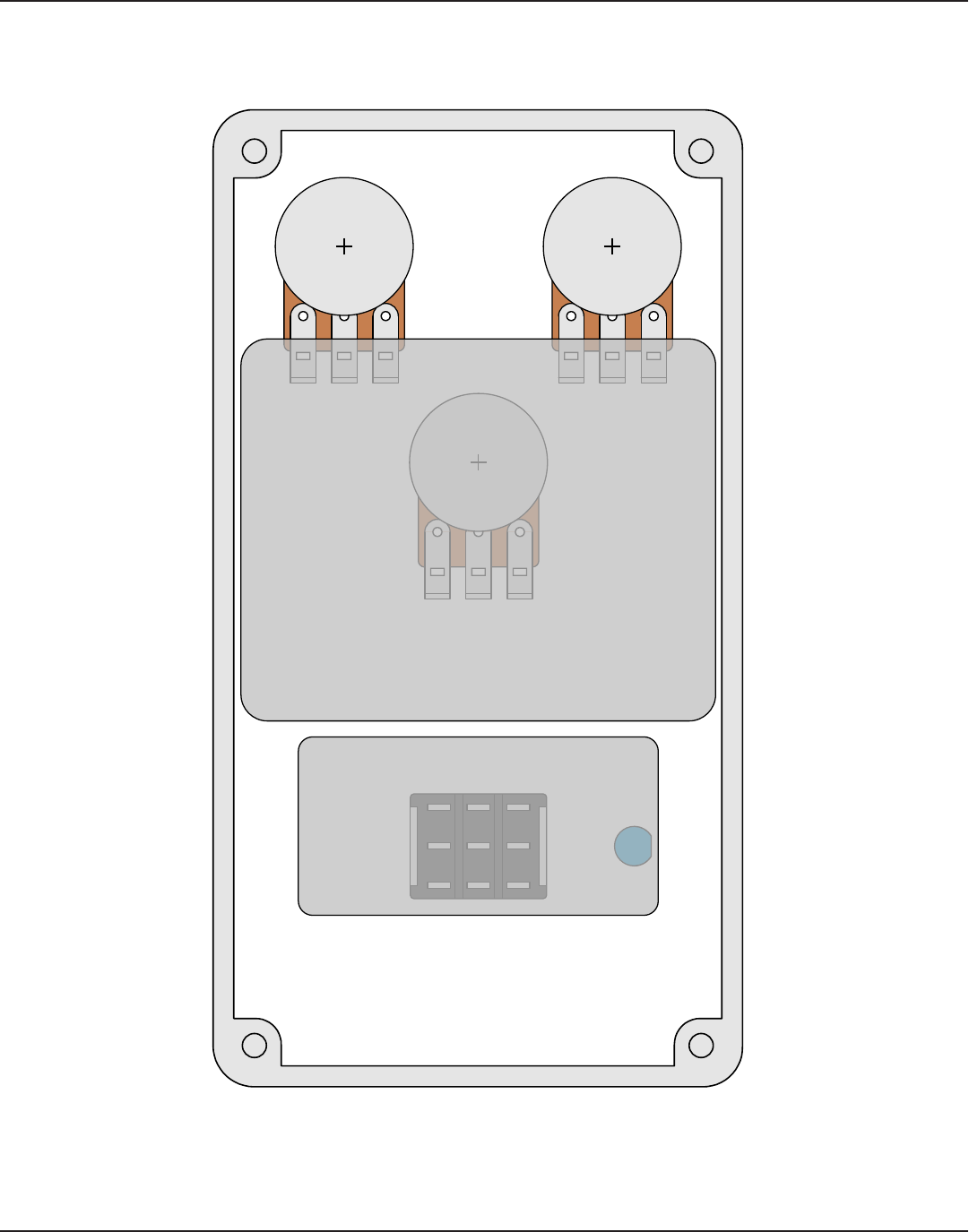
ENCLOSURE LAYOUT
Enclosure is shown without jacks. See next page for jack layout and wiring.
125B
PHOBOS GERMANIUM FUZZ 10
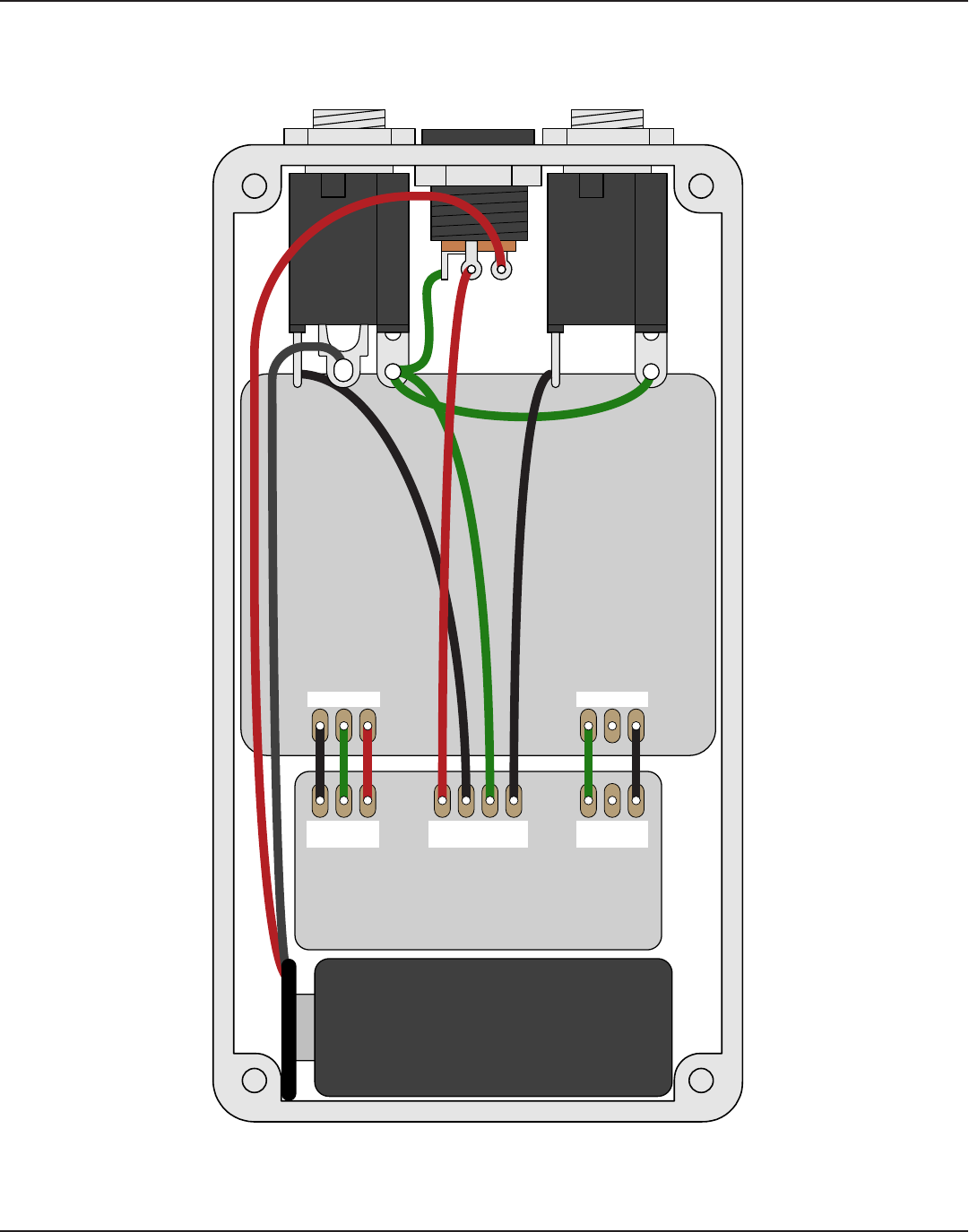
WIRING DIAGRAM
125B
IN +VGND GND N.C. OUT
PCB
IN
GND +V +V JACK GND JACK
OUTIN
GND GND PCB
OUT
Shown with optional 9V battery. If battery is omitted, both jacks can be mono rather than one being stereo.
Leave the far-right lug of the DC jack unconnected.

PHOBOS GERMANIUM FUZZ 11
LICENSE & USAGE
No direct support is offered for these projects beyond the provided documentation. It’s assumed
that you have at least some experience building pedals before starting one of these. Replacements and
refunds cannot be offered unless it can be shown that the circuit or documentation are in error.
All of these circuits have been tested in good faith in their base configurations. However, not all the
modifications or variations have necessarily been tested. These are offered only as suggestions based
on the experience and opinions of others.
Projects may be used for commercial endeavors in any quantity unless specifically noted. No
attribution is necessary, though a link back is always greatly appreciated. The only usage restrictions
are that (1) you cannot resell the PCB as part of a kit without prior arrangement, and (2) you cannot
“goop” the circuit, scratch off the screenprint, or otherwise obfuscate the circuit to disguise its source.
(In other words: you don’t have to go out of your way to advertise the fact that you use these PCBs, but
please don’t go out of your way to hide it. The guitar effects industry needs more transparency, not less!)
DOCUMENT REVISIONS
1.0.2 (2024-08-08)
Changed LEDR to 10k to work with a wider variety of LEDs.
1.0.1 (2022-10-18)
Revised biasing instructions and changed both bias trimmers to 50k to allow for easier biasing of a wider
variety of transistors.
1.0.0 (2020-07-03)
Initial release.
