
Buzzaround XL
Service Guide
This Service Guide contains:
Troubleshooting
Replacement Instructions
Multi-meter Instructions
Model GB117 Model GB147

Buzzaround XL_SG_REVA
1
Buzzaround XL_SG_REVA
2
Table of Contents
Nomenclature and Contact Information.......................................................................................................3
ABOUT THE BUZZAROUND XL SERVICE GUIDE.............................................................................4
Buzzaround XL Components....................................................................................................................4-9
Wiring Diagram..........................................................................................................................................10
SCENARIO 1: Turn the key to the on position and no power...................................................................11
SCENARIO 2: Batteries will not charge....................................................................................................12
BEEP CODES.......................................................................................................................................13-18
BEEP CODE #1 – Batteries Low (Scooter may drive slowly)...................................................................13
BEEP CODE #2 – Batteries Low (Scooter will not operate)......................................................................13
BEEP CODE #3 - High Battery Voltage....................................................................................................13
BEEP CODE #4 - Current Limit Timeout.............................................................................................13-14
BEEP CODE #5 - Brake Fault...............................................................................................................14-15
BEEP CODE #6 - Paddle Fault (out of neutral)..........................................................................................15
BEEP CODE #7 - Paddle Fault/Speed Control Fault (voltage error)....................................................16-17
BEEP CODE #8 - Motor Voltage Fault (Open/Shorted)......................................................................17-18
BEEP CODE #9 - Controller Fault.............................................................................................................18
BUZZAROUND XL REPLACEMENT INSTRUCTIONS.................................................................19-25
Drive Wheel................................................................................................................................................19
Drive Train..................................................................................................................................................19
Throttle Pot.................................................................................................................................................19
Battery........................................................................................................................................................20
Circuit Breaker............................................................................................................................................21
Battery Harness Fuse..................................................................................................................................21
Controller....................................................................................................................................................21
Main Harness..............................................................................................................................................22
Control Panel..............................................................................................................................................22
Motor/Brake................................................................................................................................................23
Front Intermediate Harness....................................................................................................................23-24
Rear Intermediate Connector......................................................................................................................24
Power Harness.............................................................................................................................................25
APPENDIX A - HOW TO USE A VOLTMETER....................................................................................26
APPENDIX B - HOW TO USE AN OHM METER..................................................................................27
Buzzaround XL_SG_REVA
3
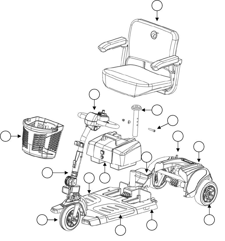
BUZZAROUND XL NOMENCLATURE
1 - Seat Assembly with arms
2 - Control Panel
3 - Battery Pack
4 - Rear Section
5 - Freewheel Lever
6 - Drive Wheel
7 - Front Section
8 - Controller (located under floor panel)
9 - Removable Anti-Slip Floor Panels (Gray/Textured)
10 - Front Wheel
11 - Tiller
12 - Front Basket
13 - Seat Post
14 - Bolt, Arc Washer, and Nut
15 - Lockup Handle
Figure 1. Buzzaround XL (Model GB117)
Contact Information
Golden Technologies
401 Bridge Street
Old Forge, PA 18518
Toll-free: 800-624-6374
Mobility Tech: x501
Lift Chair: x502
VA Tech: x505
Fax: 800-628-5165
Email: parts@goldentech.com
5
6
7
8
9
3
4
2
1
10
11
12
13
14
15

Buzzaround XL_SG_REVA
4
ABOUT THE BUZZAROUND XL™ SERVICE GUIDE
This service guide provides you with the information necessary to troubleshoot the Golden Technologies Buzzaround XL
GB117/GB147. The troubleshooting scenarios in this manual consist of procedures that enable you to systematically trace
and correct faults in the system. Appendices A and B include instructions on how to measure voltage and continuity with
a multimeter.
Before troubleshooting, check the following:
Make sure that the circuit breaker is reset.
Visually check terminals for corrosion. Check wires for missing insulation.
Make sure the battery terminals are securely tightened.
Make sure that the batteries are fully charged and are in good working order. When possible, keep sets of
known good batteries of various ratings in your shop at all times. The Buzzaround XL uses either two (2) 12AH
or (2) 22AH batteries. Problems that surface during troubleshooting are often due to the fact that the batteries are
not fully charged or can not hold their charge.
Make sure that the electrical connections are secure. Unplug the connectors and make sure all the pins in the
connectors are seated securely. If necessary, push any unseated pins back into their connector housings to securely
seat them.
If you get to a point during troubleshooting where you cannot continue, call Technical Support
at 800-624-6374.
BUZZAROUND XL COMPONENTS
The Buzzaround XL is a battery-operated scooter with a controller that monitors the system and beeps when it detects a
fault in the system. The Buzzaround XL was designed to operate within a range of between 18 - 24 volts (V) of direct
current (DC).
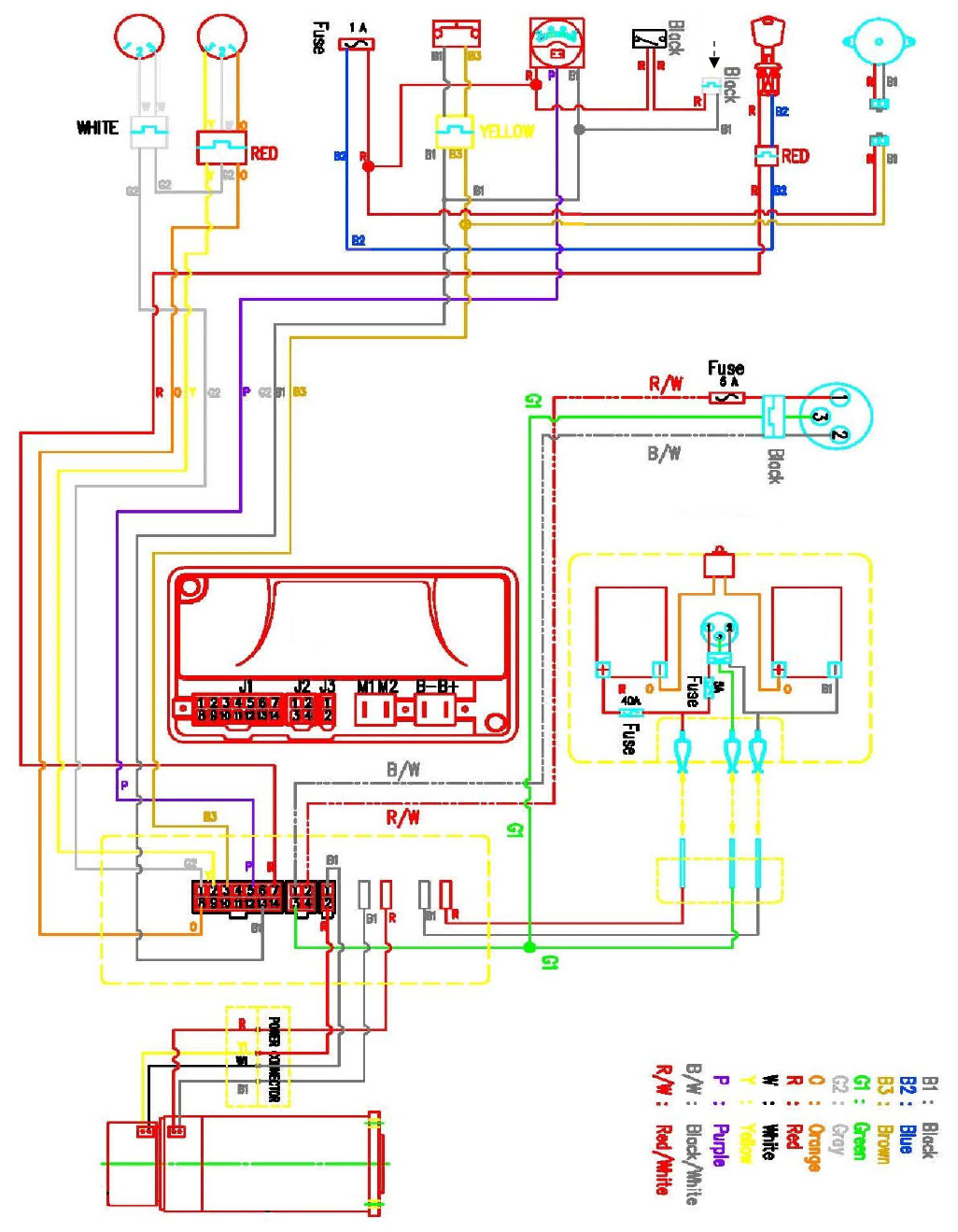
The Buzzaround XL control system is made up of the components listed below. Each of these
components is designated by its assigned number. Refer to the figure 11 (wiring diagram) on page 10.
• Circuit Breaker (1)
• 12V Batteries (2 and 3)
• Battery Harness (4)
• Power Harness (5)
• Dynamics R-Series Controller (6)
• Main Harness (7)
• Front Intermediate Harness (8)
• Rear Intermediate Connector (9)
• Motor/Brake Assembly (10)
• Brake (11)
• Control Panel - includes Speed Pot (12), Key Switch (13), Horn Button, and Battery Meter
• Throttle Pot (14)
• Charger Harness (15)
• Off-Board Battery Charger – (See figure 11 on page 9.)
Parts and service must be authorized by the Golden Technologies Service Department.
Unauthorized parts or service may void the warranty. For more information, contact the Golden Technologies
Service Department at 800-624-6374 or [email protected].
Buzzaround XL_SG_REVA
5
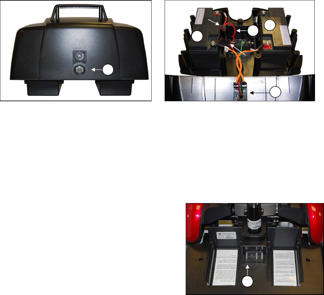
Component: Circuit Breaker - #1
Location: Mounted on the Battery Pack. See figure 2.
Function: Protects battery circuit from current overload. When the current draw exceeds the breaker rating, the circuit
breaker will open.
Connections: The circuit breaker is connected to the positive (+) terminal on one battery and the negative (-) terminal on
the other. (Note: Both circuit breaker wires are orange in color.)
Failure Signs: Opens repeatedly. May indicate failed circuit breaker or short in the wiring. May also open if the motors
are overloaded (from excessive weight, excessive uphill driving, etc).
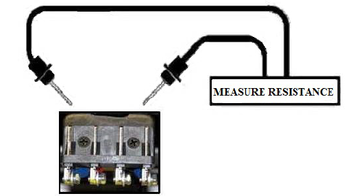
Test: Measure the resistance across the circuit breaker and the wires that connect the circuit breaker to the batteries.
Expected reading: Less than 10 ohms.
Serviceable: 30amp circuit breaker must be replaced with exact current rating.
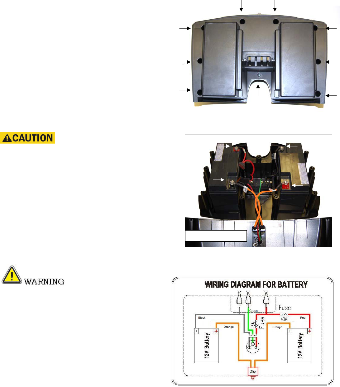
Figure 2. Battery Box Figure 3. Inside Battery Pack
Component: 2-12VDC Batteries - #2 and #3
Location: Inside the battery pack. See figure 3.
Function: Supply 24VDC to the motor and/or accessories (12VDC x 2).
Connections: Connected in series. The positive (+) terminal of one battery is connected to the negative (-) of the
other (orange wires) through the circuit breaker (1). The most positive and negative terminals are connected to the
charging port (red and black wires) and the controller through the power harness (5). Refer to figure 11 on page 10.
Failure Signs: Batteries drain quickly. Scooter runs slowly or not at all. Batteries will not charge, but charger is working
properly. Beep Code #1 or #2.
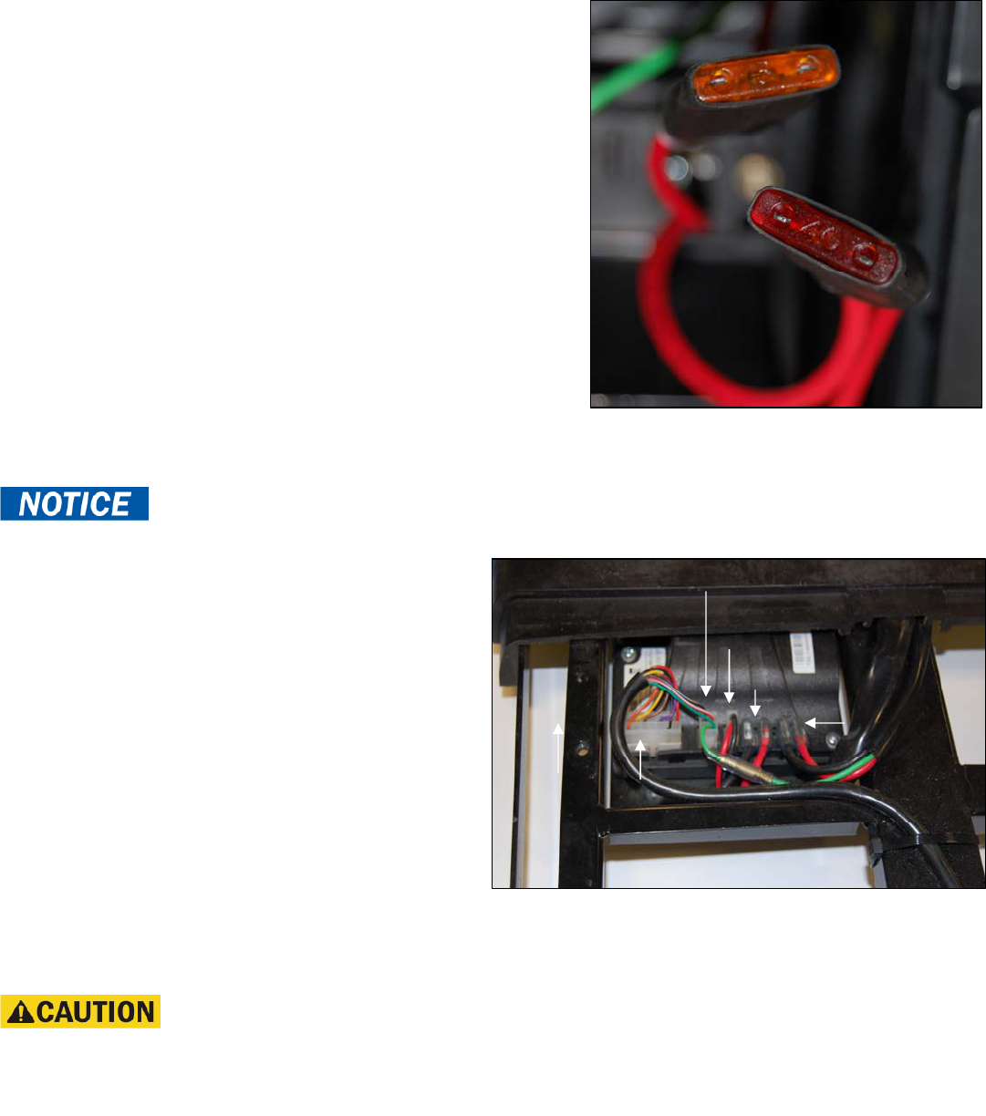
Tests: Fully charge the batteries first and load test. Make sure the contacts are not corroded. See figure 4 below and figure
16 on page 12.
Expected Readings: 12 - 14VDC each when fully charged.
Serviceable: Replace batteries as necessary.
Component: Battery Harness - #4
Location: Inside the battery pack. See figure 3.
Function: Connects the batteries to the Power Harness (5).
Provides over current protection from the battery charger
through a 5-amp inline fuse, and from the batteries through a
40-amp inline fuse.
Connections: Connected to the power harness, charger harness,
batteries, battery fuse, and charger fuse.
Refer to figure 11 on page 10.
Failure Signs: Corroded wires may cause the batteries not to
work properly. Make sure connector pins are seated properly. Figure 4. Scooter Battery Connection
Batteries will not charge if the inline fuse is blown.
Tests: Test the harness for continuity. Test the fuse for continuity.
Expected Readings: Less than 10 ohms.
Serviceable: Replace the harness as necessary. Replace inline fuse(s) with exact type and rating. See figure 3.
Circuit
Breaker
Charger Fuse
(5amp)
Charging Port
Battery Fuse (40amp)
1
2
3
4
15
5
Buzzaround XL_SG_REVA
6
Figure 5. Controller
Component: Power Harness - #5
Location: Mounted to the front frame – located under the battery pack. See #5 on figure 4.
Function: Connects the battery pack to the controller.
Connections: Connects to the battery pack to the controller (inhibit), (Bat -), (Bat +) connections.
Refer to figure 11 on page 10.
Failure Signs: Charger connected to the battery pack and the scooter runs, inhibit problem or no power to the controller.
Tests: Test harnesses for continuity. Check connectors. Make sure the contacts are not corroded and are seated properly.
Expected Readings: Continuity (less than 10 ohms).
Serviceable: Replace as necessary.
Component: Controller - #6
Location: Mounted to the front frame - under the floor shroud. See #1 on figure 5.
Function: Controls and monitors the system. Uses a series of beeps when something in the system is out of range.
Connections: Connected to the main harness, charger & inhibit, brake, motor (M1M2), battery (B-B+). See figure 5.
Refer to figure 11 on page 10.
Failure Signs: Beep Code #9. No power to the control panel or the motor.
Tests: Test for voltage coming into and out of the controller.
Expected readings: Battery voltage.
Serviceable: Replace as necessary.
Component: Main Harness - #7
Location: Inside the tiller and under the frame. See #2 on figure 5.
Function: Provides connectivity for the tiller components and the controller.
Connections: Connected to the controller, and control panel. Refer to figure 11 on page 10.
Failure Signs: Scooter will not run.
Tests: Test for voltage and continuity. Check connectors. Make sure the pins are not corroded and are seated properly.
Expected readings: Battery voltage. Continuity (less than 10 ohms).
Serviceable: Replace as necessary.
2
1
Char
g
er & inhibit
M1 & M2
Brake
Bat- Bat+
Main
Harness
Buzzaround XL_SG_REVA
7
Component: Front Intermediate Harness - #8
Location: Mounted on the front frame. See figure 6.
Function: Provides connectivity between the motor/brake
and the controller.
Connections: Connected to the rear intermediate connector (9)
and the controller (6). Refer to figure 11 on page 10.
Failure Signs: Scooter will run slowly or not at all.
Tests: Test for voltage and continuity. Check connectors.
Make sure the pins are not corroded and are seated properly.
Expected readings: Continuity (less than 10 ohms).
Serviceable: Replace as necessary.
Component: Rear Intermediate Connector - #9
Location: Mounted on the rear frame. See figure 7.
Function: Provides connectivity between the motor/brake Figure 6. Front Intermediate Harness
and the controller.
Connections: Connected to the front intermediate
harness (8) and the motor/brake assembly (10).
Refer to figure 11 on page 10.
Failure Signs: Scooter will run slowly or not at all.
Tests: Test for voltage and continuity. Check connectors.
Make sure the contacts are not corroded.
Expected readings: Continuity (less than 10 ohms).
Serviceable: Replace as necessary.
Component: Motor/Brake Assembly - #10
Location: Mounted on the transaxle. See #1 on figure 8.
Function: Drives the scooter.
Connections: Connected to the rear intermediate connector (9)
and the brake (11). Refer to figure 11 on page 10.
Failure Signs: Scooter runs slowly or not at all. Figure 7. Rear Intermediate Connector
Tests: Test for internal resistance in motor. Test motor
wires for continuity. See Beep Codes #5 and #8.
Expected readings: Internal motor resistance is
0.8 ohms – 1.5 ohms. Brake resistance is 45 ohms – 52 ohms.
Serviceable: Replace the motor/brake assembly.
Component: Brake - #11
Location: Mounted on the end of the motor. See #2 on figure 8.
Function: Keeps the motor from moving when the power is off.
Connections: Connected to the rear intermediate connector (9).
Refer to figure 11 on page 10.
Failure Signs: Scooter runs slowly or not at all.
Tests: Test for internal resistance. See Beep Code #5 on page 14
and Beep Code #8 on page 17.
Expected readings: Brake resistance is 45 ohms – 52 ohms.
Serviceable: Replace the motor/brake assembly.
Figure 8. Motor/Brake Assembly
1 2
Buzzaround XL_SG_REVA
8
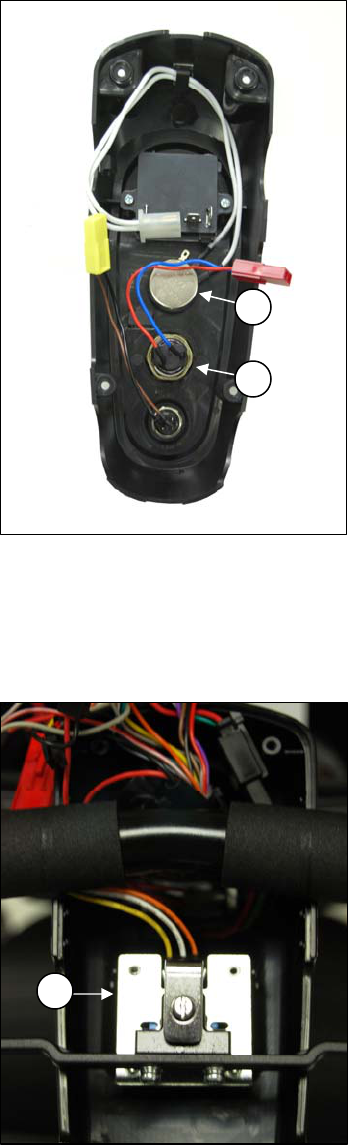
Component: Speed Pot (Potentiometer) - #12
Location: Mounted on the control panel. See #1 on figure 9.
Function: The speed pot uses variable resistance to control
the speed of the scooter.
Connections: Connected to the main harness through the control panel harness.
Failure Signs: Beep Code #7
Tests: Call Tech Support
Expected readings: Depends on speed pot position.
Serviceable: Yes. Replace the speed pot.
Component: Key Switch - #13
Location: Mounted on the control panel. See #2 on figure 9.
Function: Completes the circuit to provide power to the motor.
Connections: Connected to the main harness through the
control panel harness.
Failure Signs: No power when the key is in the “ON” position.
Tests: Continuity when the key is in the “ON” position. Make
sure the connector pins are seated properly.
Expected readings: Less than 10 ohms.
Serviceable: Yes. Replace the key switch.
Component: Throttle Pot (Potentiometer) - #14
Location: Below the control panel. See #1 on figure 10. Figure 9. Control Panel (Back)
Function: The throttle pot uses variable resistance
to control speed and direction of travel by varying voltage.
Connections: Connected to the main harness (7) and 1amp in-line fuse.
Refer to figure 11 on page 10.
Failure Signs: Beep Codes #6 and #7.
Tests: Test resistance across pins 1, 2, and 3 on the throttle pot.
Expected readings: Depends on direction of deflection.
Serviceable: Replace as necessary.
Component: Charger Harness - #15
Location: Two locations.
1. Inside the battery pack. See #15 on figure 3 on page 5.
2. Inside the tiller. See #15 on figure 11 on page 10.
Function: Connects the charger to the batteries.
Connections: Connected to the battery harness (4), power harness (5),
and the charger not shown. Refer to figure 11 on page 10.
Failure Signs: Batteries will not charge.
Tests: Test for voltage and continuity. Check connectors.
Make sure the pins are not corroded and are seated properly.
Expected readings: Continuity (less than 10 ohms).
Serviceable: Replace the harness as necessary.
Figure 10. Throttle Pot
1
2
1
Buzzaround XL_SG_REVA
9
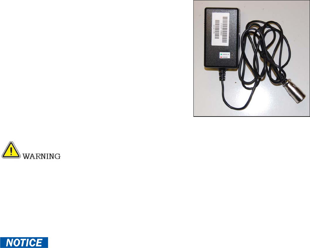
Component: Off-Board Charger
Location: Stored inside a pouch on the seatback.
Function: Recharges batteries.
Connections: Connects to the charger port on the battery pack
or the charger port on the tiller. The tiller port is connected to the
batteries through the main harness. Refer to figure 11 on page 10.
Failure Signs: Charger power LED does not go on. Batteries
will not charge.
Tests: With the charger connected to the charger port, measure
voltage across the most negative (black wire) and most positive
(red wire) battery terminals. While observing the voltage reading,
plug the charger into the wall outlet and make sure the voltage
reading increases.
Expected readings: Battery voltage first, approximately 27 volts
when fully charged. Then voltage should increase to approximately
29.5 volts with the charger connected and plugged into the wall outlet.
Also, refer to the charger test on page 12. Test charger harness and
fuse for continuity.
Serviceable: Replace if necessary. Figure 11. Off-Board Battery Charger
Only use the charge that was supplied with the scooter. The charger was specifically
designed and tested for the product it came with.
Some Off-Board Battery Chargers may have a switch that enables them to be used with either 110
VAC or 230 VAC. This switch is typically located on the end of the charger. Some may also have a removable glass
fuse. *Fuses must be replaced with exact type and rating.*
Buzzaround XL_SG_REVA
10
Figure 11. Buzzaround XL Wiring Diagram
LED Light
Speed Pot (12)
Throttle Pot (14)
Key Switch (13)
Horn
LED Light Switch
Battery Meter
Horn Switch
Charger Harness (15)
Dynamic R-Series
Controller (6)
30 AMP
Circuit Breaker (1)
Battery (2)
12V
Battery (3)
12V
Battery Box
Battery Harness (4)
Power Harness (5)
Main Harness (7
)
Front Intermediate Harness (8)
Rear Intermediate Connector (9)
Motor / Brake
Assembly (10)
Brake (11)
Buzzaround XL_SG_REVA
11
SCENARIO 1: TURN THE KEY TO THE ON POSITION AND NO POWER
Put the key into the key switch and turn to the on position. There is no power to the control panel. The horn does not work
and the battery condition meter does not work. Battery voltage travels from the batteries, through the controller and the
key switch. The test below will verify that there is battery voltage at the batteries, the controller, the main harness, and the
key switch.
Make sure that the batteries are fully-charged and connected properly. Refer to the battery connection diagram inside the
battery pack. You can also refer to figure 11 on page 10. If the batteries will not charge, go to “Scenario 2: Batteries will
not charge.”
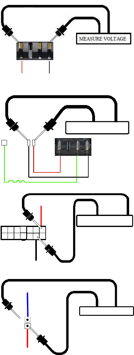
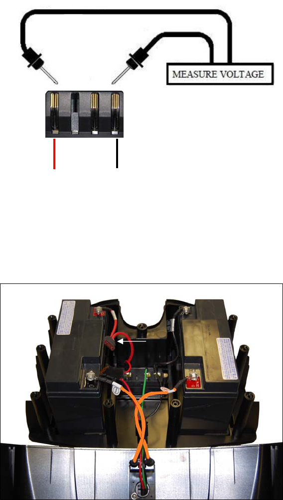
Check Battery Voltage at Battery Pack.
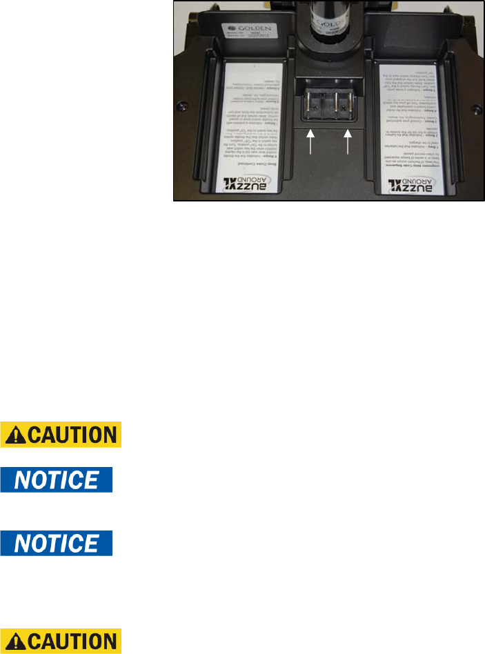
1. Remove the battery pack.
2. Measure voltage across the two outside terminals on the connector.
See figure 12.
• 24VDC (or battery voltage?) - Go to the next step.
• More than 16VDC? - Try to recharge the batteries.
Load test and replace if necessary.
• 0VDC? - Check main circuit breaker (1) and battery
harness (4) for continuity.
Check Voltage at Power Harness.
3. Remove the two gray floor panels by pushing them up from
the underside of the scooter frame.
4. Remove the four screws fastening the floor shroud.
5. Disconnect the power harnesses (5) from the controller.
6. Reinstall the battery pack.
7. Measure voltage across the red B+ and black B- wires. See figure 13.
• 24VDC (or battery voltage?) - Go to the next step.
• 0VDC? - Check power harness for continuity.
Replace as necessary.
Figure 13.
Check Voltage Out of Controller.
8. Reconnect the power harness to the controller.
9. Insert the multimeter probes into the terminal with the red
wire (pin 7) and the terminal with the black wire (pin 13)
on the back of the main harness connector (7). See figure 14.
• 24VDC (or battery voltage?) - Go to the next step.
• 0VDC? - Replace the controller.
Check Voltage at Main Harness.
10. Open the control panel.
11. Disconnect the red key switch connector harness (13).
Figure 14.
12. Measure voltage across the two pins on the male connector
(red and blue wires). See figure 15.
• 24VDC (or battery voltage?) - Check continuity across the
key switch. No continuity? – Replace key switch.
Continuity? - Replace the control panel.
• 0VDC? – Check the fuse for continuity. No continuity? –
Replace the 1 amp fuse. Refer to Figure 11 on page 10.
Continuity? - Replace the main harness (7).
Figure 15.
Figure 12.
RED +
RED +
RED +
BLACK -
BLACK -
GREEN
RED +
BLACK -
BLUE - RED +
BACK
VIEW
MEASURE VOLTAGE
MEASURE VOLTAGE
MEASURE VOLTAGE
GREEN
Buzzaround XL_SG_REVA
12
SCENARIO 2: BATTERIES WILL NOT CHARGE
Most battery chargers need to “see” at least 16VDC at the charger port. Otherwise, they may not send a charging
current to the batteries. This test will ensure that the battery voltage is making it to the charger port. You will need
to check battery voltage and wiring harness continuity inside the battery pack.
Check Battery Charger Voltage.
1. Remove the battery pack.
2. Plug the charger into the charger port and then into a wall outlet.
3. Measure voltage across the two outside terminals on connector (4). See figure 16. Does the voltage increase?
• Yes? - Load test the batteries and replace as necessary.
• No? - But there is voltage. If the voltage is lower than 16VDC, then replace the batteries. If the voltage is 16VDC or
greater, then go to the next step.
• No? - And there is no voltage. Open the battery pack and check the circuit breaker, battery harnesses, and 40 amp
fuse for continuity. Replace the individual components as necessary.
Figure 16. Connector 4
4. Open the battery pack.
5. Check the battery harness fuse for continuity.
• Less than 10 ohms? – Replace the charger harness.
• Open? – Replace the 5 amp fuse. See figure 17.
Figure 17. Battery Harness Fuse
RED +
BLACK -
Fuse
Buzzaround XL_SG_REVA
13
BEEP CODES
The controller uses audible beeps to indicate the status of the system. When the controller notices that there is
a malfunction in the system, it will beep a code when the power is on. For example, when it beeps five times and stops
that indicates beep code #5 – Brake Fault.
The following beep codes are used to help diagnose system errors:
Beep Code #1 – Batteries Low (Scooter will operate)
Beep Code #2 – Batteries Very Low (Scooter will not operate)
Beep Code #3 – High Battery Voltage
Beep Code #4 – Current limit timeout
Beep Code #5 – Brake Fault
Beep Code #6 – Paddle Fault (out of neutral)
Beep Code #7 – Throttle Pot/Speed Pot Fault
Beep Code #8 – Motor Voltage Fault (Open/Shorted)
Beep Code #9 – Controller Fault
BEEP CODE #1 – BATTERIES LOW (SCOOTER MAY DRIVE SLOWLY)
This Beep Code occurs when the battery voltage drops below a certain level. Recharge the batteries immediately.
If the batteries will not recharge, then load test them or refer to “Scenario 2: Batteries will not Charge”, on page 12.
BEEP CODE #2 – BATTERIES LOW (SCOOTER WILL NOT OPERATE)
This Beep Code occurs when the battery voltage drops lower than Beep Code #1. Recharge the batteries immediately.
If the batteries will not recharge, load test them or refer to “Scenario 2: Batteries will not Charge”, on page 12.
BEEP CODE #3 - HIGH BATTERY VOLTAGE
This Beep Code occurs when the battery voltage climbs above 26VDC.
1. Insert the key into the key switch and turn it to the on position. Allow the battery level to drop. Do not allow the battery
voltage to fall into the red area on the battery meter.
2. Check the battery charger. Make sure it is an approved charger.
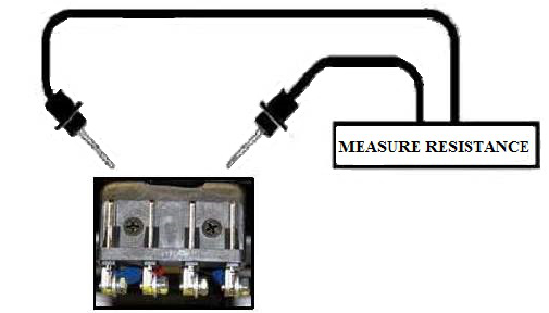
BEEP CODE #4 - CURRENT LIMIT TIMEOUT
This Beep Code occurs when the motor has been exceeding its maximum current rating for too long. This may be due to a
faulty motor, poor battery condition, excessive uphill driving, or excessive weight. First turn off the scooter and allow it to
cool for ten minutes. If this does not work, use the following procedure.
Inspect Motor/Brake and Rear Intermediate Connector.
1. Remove the seat.
2. Remove the battery pack.
3. Separate the front and rear halves of the scooter, and inspect the connection between the motor/brake assembly (10) and
the rear intermediate connector (9). Is there visible damage, discolored or melted wires? Refer to figure 11 on page 10.
• Yes? - Replace the motor/brake assembly or rear intermediate connector as necessary.
• No? - Go to the next step.
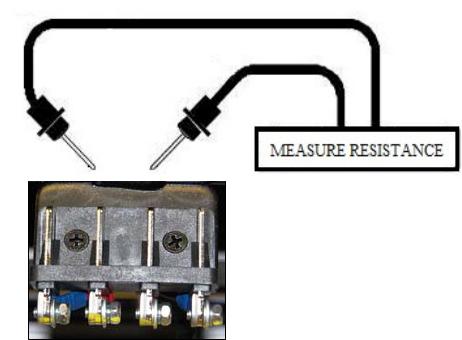
Check Motor Resistance at Motor.
4. Measure resistance across the two outside pins on connector (9)
that have the thick black wire and the thick red wire.
(Internal resistance of the motor). See figure 18.
• 0.8 ohms – 1.5 ohms but not shorted? – Go to the next step.
• Out of that range? – Replace the motor/brake assembly.
Figure 18. Connector 9
BLACK RED
Buzzaround XL_SG_REVA
14
Check for Continuity on the Front Intermediate Harness.
5. Remove the two gray floor panels by pushing them up from the underside of the scooter frame.
6. Remove the four screws fastening the floor shroud.
7. Disconnect the front intermediate harness (8) from the controller. Refer to figure 11 on page 10.
8. Make sure that the pins are not damaged or discolored. On the front intermediate harness, check the continuity between
the M1 and M2 (thick red and black) wires and the two outside pins on connector 8.
• 10 ohms or less? – Replace the controller.
• Open? – Go the next step.
9. Inspect the front intermediate harness (8) and rear intermediate connector (9). Refer to figure 11 on page 10.
Are they discolored, corroded, or damaged?
• Yes? - Replace as necessary.
• No? - Go to the next step.
10. Take a quarter and slide into each contact
on the front intermediate harness connector (8). See figure 19.
Does each contact hold the quarter firmly in place?
• No? - Replace the front intermediate harness (8).
• Yes? - Go to the next step.
11. Check the rear intermediate connector (9) and the
motor/brake harnesses connected to connector (9).
• No damage or discoloration? – Replace the controller.
• Damaged or discolored? – Replace as necessary.
Figure 19. Quarter Test (Connector 8)
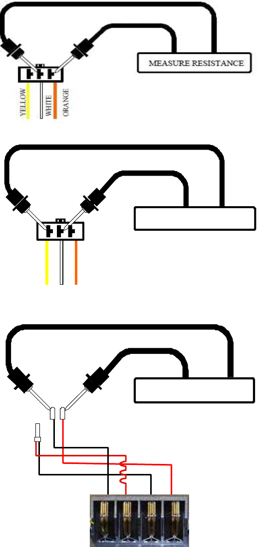
BEEP CODE #5 - BRAKE FAULT
This Beep Code occurs because the park brake release switch is active or the park brake may be faulty.
Check the Park Brake Position
1. Turn the key to the off position.
2. Disengage and then re-engage the park brake.
3. Turn the key to the on position. Did the beep code clear?
• Yes? - OK.
• No? - Go to the next step.
Check Park Brake Resistance at the Controller.
4. Remove the seat.
5. Remove the battery pack.
6. Remove the two gray floor panels by pushing them up
from the underside of the scooter frame.
7. Remove the four screws fastening the floor shroud.
8. Disconnect the (J3) connector of the front intermediate harness (8)
from the controller. Refer to figure 11 on page 10.
9. Make sure that the pins on J3 are seated properly. Measure resistance
across (J3) pin 1 and pin 2 on the front intermediate harness (8)
with the park brake engaged. See figure 20.
• 45 ohms – 52 ohms? – Replace the controller.
• Shorted or open? – Go to the next step.
Figure 20. Connector J3
RED BLACK
Buzzaround XL_SG_REVA
15
Check for Continuity on the Front Intermediate Harness.
10. Separate the front and rear halves of the scooter.
11. Measure resistance from the connector (J3) pin 1 an pin 2 to the two middle pins on the connector of the front
intermediate harness (8).
• 10 ohms or less? – Go to the next step.
• Open? – Replace the front intermediate harness (8).
12. Inspect the front intermediate harness (8) and rear intermediate connector (9). Refer to figure 11 on page 10.
Are they discolored, corroded, or damaged?
• Yes? - Replace harness/es as necessary.
• No? - Go to the next step.
13. Take a quarter and slide into each contact on the front intermediate harness connector (8). See figure 19 on page 14.
Does each contact hold the quarter firmly in place?
• No? - Replace the front intermediate harness (8).
• Yes? - Go to the next step.
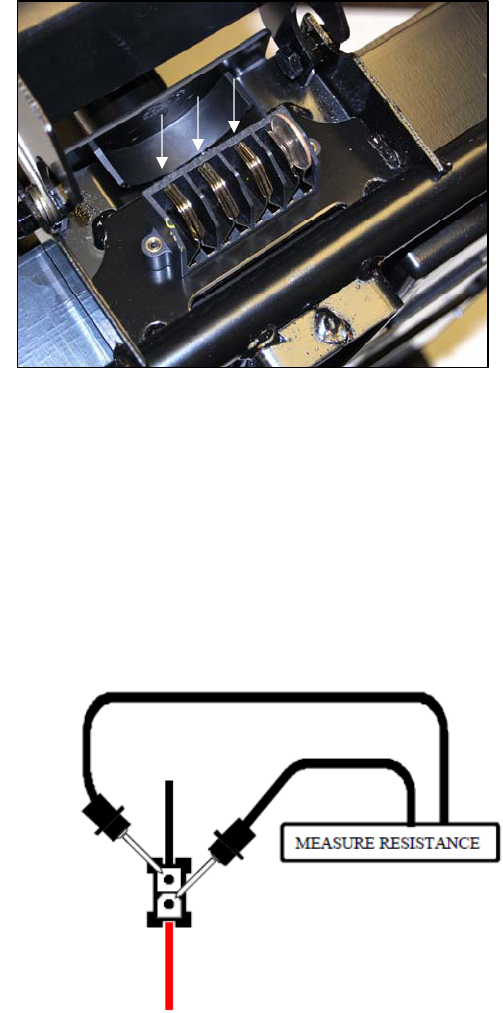
Check Resistance at Park Brake.
14. Measure resistance across the two inside pins on the
intermediate harness connector (9) with park brake
engaged. See figure 21.
• 45 ohms – 52 ohms? – Replace the controller.
• Out of range? – Replace the motor/brake assembly.
• Open? – Check the connections at connector (9).
• Shorted? – Replace the motor/brake assembly.
Figure 21. Connector 9
BEEP CODE #6 - PADDLE FAULT (OUT OF NEUTRAL)
This Beep Code means that the throttle control lever was not in the neutral position when the key is turned to the
on position.
1. Turn the key to the off position.
2. Make sure that the paddle pot is not obstructed and it can return to the neutral (center) position.
3. Move the throttle pot forward and then reverse. Make sure that it is not obstructed. Does it spring back to the neutral
position?
• Yes? – Go to the next step.
• No? – Check for obstructions. Adjust if necessary. Replace if the adjustment does not work or if there are no
obstructions.
4. Turn the key to the on position. Does the code return?
• No? – OK
• Yes? – Go to Beep CODE #7 to test the paddle pot.
YELLOW
WHITE
Buzzaround XL_SG_REVA
16
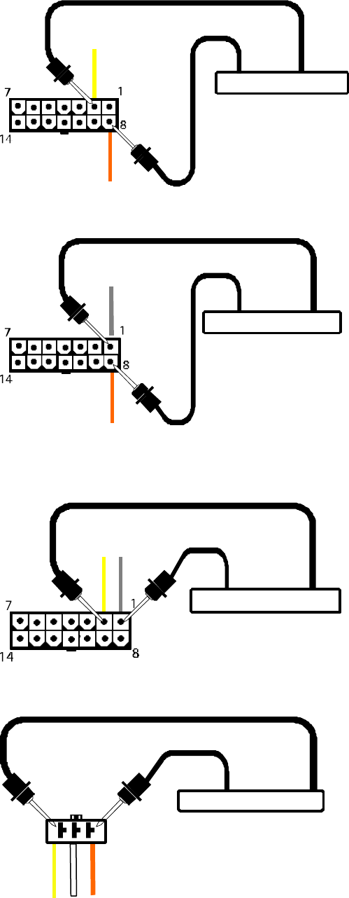
BEEP CODE #7 - THROTTLE POT/SPEED CONTROL FAULT
This Beep Code occurs because there is a fault with the throttle pot,
speed pot, or the associated wiring.
Check Throttle Pot Resistance at Controller.
1. Remove the seat.
2. Remove the battery pack.
3. Remove the two gray floor panels by pushing them up
from the underside of the scooter frame.
4. Remove the four screws fastening the floor shroud.
5. Turn the speed pot to full rabbit.
6. Set your multimeter to measure resistance. Figure 22. Connector 7
7. Disconnect the main harness (7) from the
controller. Refer to figure 11 on page 10.
8. Insert multimeter probes into the main harness
connector 7 at pin 8 and pin 2 (orange wire and yellow wire).
See figure 22.
• 5k ohm ±10%? – Replace the controller.
• Outside that range? - Go to the next step.
9. Insert the multimeter probes into the main
harness connector 7 at pin 1 and pin 8
(gray wire and orange wire). See figure 23.
Note the resistance reading. Insert the multimeter probe
into the main harness connector at pin 1 and pin 2
(gray wire and yellow wire). See figure 24.
Note the resistance reading. Figure 23. Connector 7
• Are both readings within 500 ohms of each
other? - Replace the controller.
• Are either of the readings outside that range? - Go
to the next step.
Check Throttle Pot Resistance at Throttle Pot.
10. Open the control panel.
11. Disconnect the main harness (7) from
the throttle pot (14). Note: This is a red connector
with three wires, yellow, white, and orange.
Refer to figure 11 on page 10.
12. Insert multimeter probes into the throttle pot Figure 24. Connector 7
connector (14) at the yellow wire and the orange
wire (outside two pins). See figure 25.
• 5k ohm ±10%? - go to the next step.
• Outside that range? - Replace the throttle pot.
Figure 25. Connector 14
ORANGE
YELLOW
ORANGE
WHITE
ORANGE
GRAY
YELLOW
YELLOW
7 FRONT
7 FRONT
MEASURE RESISTANCE
MEASURE RESISTANCE
MEASURE RESISTANCE
GRAY
7 FRONT
MEASURE RESISTANCE
Buzzaround XL_SG_REVA
17
13. Insert the multimeter probes into the throttle pot
connector (14) at the orange wire and the white wire.
See figure 26. Note the resistance reading.
Insert the multimeter probes into the
throttle pot connector (14) at the yellow wire
and the white wire. See figure 27. Note the resistance reading.
• Are both readings within 500 ohms of
each other? - Go to the next step.
• Are either of the readings outside that
range? – Replace the throttle pot. Figure 26. Connector 14
14. Check the orange, gray, and yellow wires on
the main harness (7) for continuity.
• 10 ohms or less on each one? - Replace the
control panel.
• Open on any wire? - Replace the main harness.
BEEP CODE #8 - MOTOR VOLTAGE FAULT (OPEN)
This Beep Code occurs when there is an internal problem
with the motor or its wiring.
Check Motor Resistance at Controller. Figure 27. Connector
14
1. Remove the seat.
2. Remove the battery pack.
3. Remove the two gray floor panels by pushing them up
from the underside of the scooter frame.
4. Remove the four screws fastening the floor shroud.
5. Disconnect the (M1 and M2) connections on the
front intermediate harness (8) from the controller.
Refer to figure 11 on page 10.
6. Measure resistance across the front intermediate
harness (M1 and M2). See figure 28.
• 45 ohms – 52 ohms? – replace the controller.
• Out of that range? – Go to the next step.
Check for Continuity on the Front Intermediate Harness.
7. Separate the front and rear halves of the scooter.
8. Inspect the front intermediate harness connector (8).
Discolored, corroded, or damaged?
• Yes? - Replace as necessary.
• No? - Go to the next step.
9. Check the continuity between M1 and connector 8, Figure 28. Connectors M1M2, J3, and 8
and M2 and connector 8. Refer to figure 11 on page 10.
• 10 ohms or less? – Go to the next step.
• Open? – Replace the front intermediate harness (8).
10. Take a quarter and slide into each contact on the front intermediate harness connector (8). See figure 19 on page 14.
Does each contact hold the quarter firmly in place?
• No? - Replace the front intermediate harness (8).
• Yes? - Go to the next step.
ORANGE
YELLOW
WHITE RED
BLACK
BLACK
RED
MEASURE RESISTANCE
MEASURE RESISTANCE
M1 M2
J3
8
Buzzaround XL_SG_REVA
18
Check Motor Resistance at Motor.
11. Measure resistance across the two outside pins on connector (9) that have the thick black wire and the thick
red wire. (Internal resistance of the motor). See figure 29.
• 0.8 ohms – 1.5 ohms? – Replace the controller.
• Out of range? – Replace the motor/brake assembly.
• Open? – Check the connections at connector (9).
• Shorted? – Replace the motor/brake assembly.
BEEP CODE #9 - CONTROLLER FAULT
This Beep Code means that the controller has an internal fault.
1. Remove the key from the key switch and allow
the controller to cool down. If the code continues,
then replace the controller.
Figure 29. Connector 9
RED BLACK
Buzzaround XL_SG_REVA
19
BUZZAROUND XL REPLACEMENT INSTRUCTIONS
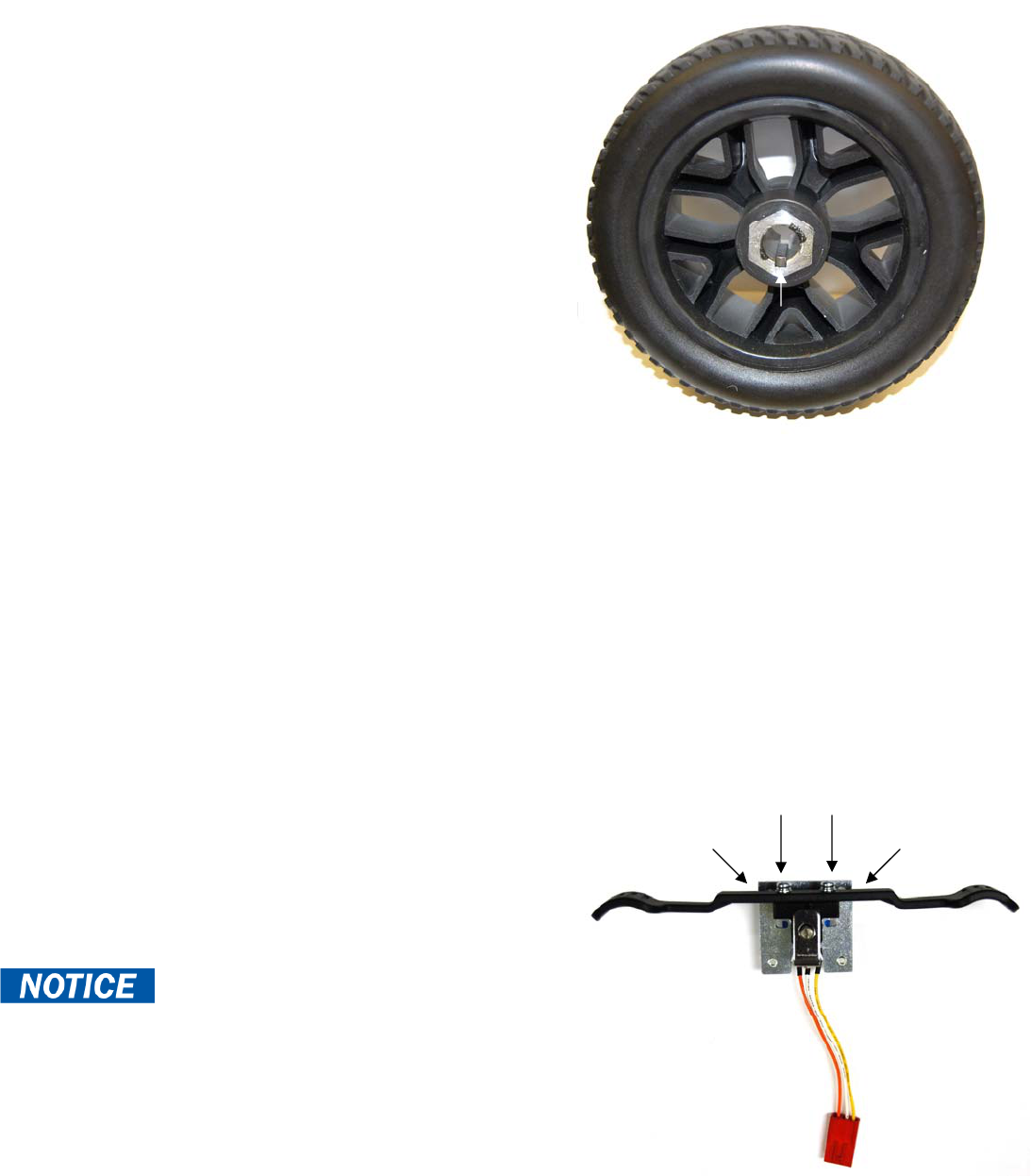
DRIVEWHEEL REPLACEMENT
Tools needed: 13mm socket, frame blocks.
1. Place the freewheel lever into the engaged position.
2. Remove the key from the key switch.
3. Place the rear of the scooter onto blocks.
4. Remove the center cap.
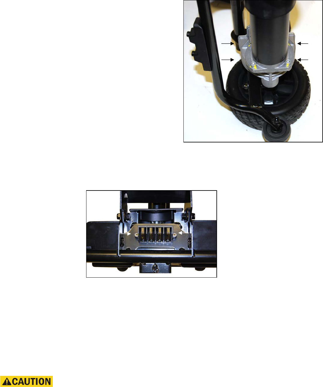
5. Remove the bolt, split washer, and washer that fasten
the wheel to the axle. Make sure you retain the axle key.
See figure 30.
6. Place a new wheel onto the axle.
Make sure that the axle key is reinstalled in its
original position.
7. Reinstall the hardware removed in step 5 and
tighten securely.
8. Reinstall the center cap.
DRIVETRAIN REPLACEMENT
Tools needed: 13mm Socket, 6mm Allen wrench
1. Place the freewheel lever in the engaged position. Figure 30. Drive Wheel Axle Key
2. Remove the key from the key switch.
3. Remove the seat.
4. Remove the battery pack.
5. Loosen the drive wheel nuts on both the left and right sides, which fasten the wheels to the axle.
6. Separate the front and rear frames.
7. Remove the drive wheels. Make sure you retain the axle keys.
8. Remove the drive train from the rear frame.
9. Install the drive wheels onto the new drive train.
10. Install the new drive train onto the rear frame.
11. Connect the rear and front frames.
12. Reinstall the battery pack.
13. Reinstall the seat.
THROTTLE POT REPLACEMENT
Tools needed: Slotted screwdriver, Phillips screwdrivers
1. Place the freewheel lever in the engaged position.
2. Remove the key from the key switch.
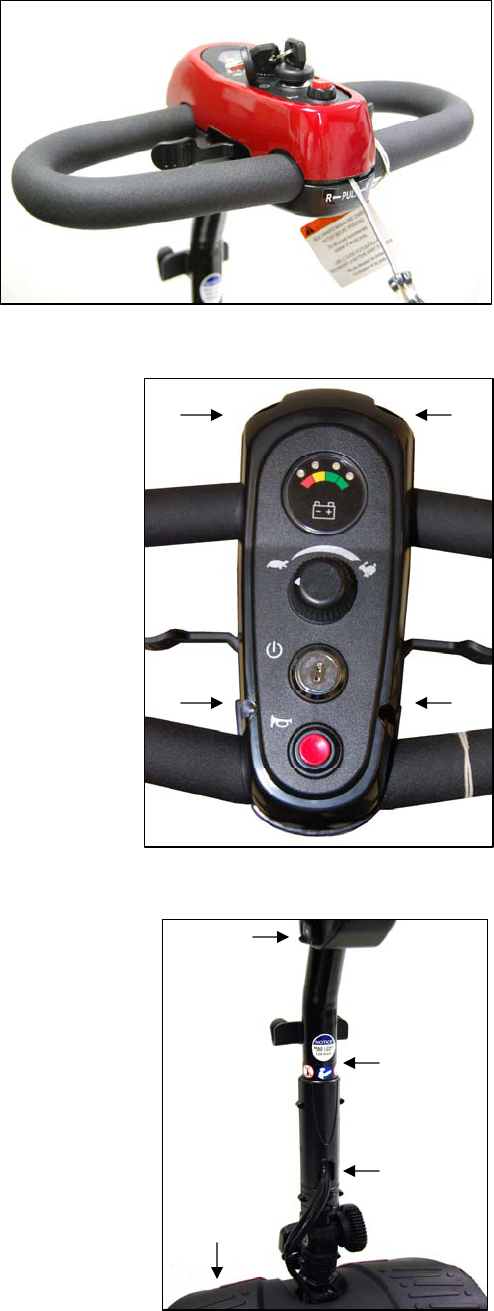
3. Use a slotted screwdriver to remove the control panel cover.
4. Separate the control panel halves by removing the (4)
Phillips screws.
At this point the plastic paddle can be replaced by
removing (2) screws. See figure 31.
5. Unplug the throttle pot harness.
6. Remove the (2) screws that fasten the throttle pot assembly.
7. Install the new throttle pot assembly.
8. Connect the throttle pot harness.
9. Reassemble the control panel halves.
10. Install the control panel cover.
Figure 31. Throttle Pot
Axle Key
Paddle Screws
Securement
Screws
Securement
Screws
Buzzaround XL_SG_REVA
20
BATTERY REPLACEMENT
Tools needed: Phillips screwdriver, 8mm wrench
1. Place the freewheel lever in the engaged
position.
2. Remove the key from the key switch.
3. Remove the seat.
4. Remove the battery pack.
5. Position the battery pack so that the screw heads
are facing up. See figure 32.
6. Remove the (9) screws that fasten the
battery pack together. See figure 32.
7. Turn the battery pack over so that the screw
holes are facing down and remove the top of the
of the battery pack. See figure 33.
Figure 32. Battery Pack (bottom side)
Note the position of the batteries and the
battery wires. Make sure that you position them in the exact
same place during assembly.
9. Remove the (-) and (+) wires from one battery.
10. Remove the battery from the pack.
11. Repeat steps 9 and 10 for the opposite battery.
12. Place a new battery into the bottom half of the
battery pack. Make sure that the terminals are
facing as shown. See figure 33.
13. Connect the (-) and (+) wires and tighten securely.
14. Place the second new battery into the bottom half of
the battery pack with the terminals facing as shown.
See figure 33. Figure 33. Inside Battery Pack
Prevent electrical shock!
Make sure hat you connect the batteries according to
the battery diagram. See figure 34.
15. Connect the (-) and (+) wires and tighten securely.
16. Place the top half of the battery pack onto the bottom.
17. Turn the battery pack over.
18. Reinstall the (9) screws that fasten the
top and bottom halves of the battery pack together.
19. Reinstall the battery pack.
Figure 34. Battery Diagram
INSIDE BATTERY PACK
Batter
y
Pac
k
To
p
Terminals
Terminals
Buzzaround XL_SG_REVA
21
CIRCUIT BREAKER REPLACEMENT
Tools needed: Phillips screwdriver, 17mm socket
1. Place the freewheel lever in the engaged position.
2. Remove the key from the key switch.
3. Remove battery pack.
4. Remove the (9) screws that fasten the battery pack together.
5. Open the battery pack.
6. Remove the circuit breaker cover and pull the breaker from the
plastic cover.
7. Remove the (2) wires connected to the circuit breaker.
8. Install the new circuit breaker.
9. Reassemble the battery pack halves together.
10. Reinstall the battery pack.
BATTERY HARNESS FUSE REPLACEMENT
Tools needed: Phillips screwdriver
1. Place the freewheel lever in the engaged position.
2. Remove the key from the key switch.
3. Remove the battery pack.
4. Remove the (9) screws that fasten the battery pack together. Figure 35. Battery Pack Fuses
6. Remove the fuse from the fuse holder.
8. Install a new fuse into the fuse holder.
Fuse(s) must be replaced with exact type and rating.
9. Reassemble the battery pack halves together.
10. Reinstall the battery pack.
CONTROLLER REPLACEMENT
Tools needed: Phillips screwdriver
1. Place the freewheel lever in the engaged position
2. Remove the key from the key switch.
3. Remove the seat.
4. Remove the battery pack.
5. Remove the (2) gray textured floor inserts
by lifting them up from each side of the floor shroud.
6. Remove the floor shroud by removing the (4)
screws securing it to the frame.
7. Remove the (2) screws that attach the controller
to the frame. Figure 35. Controller
8. Install the new controller onto the frame.
9. Reconnect the main, motor, brake, and battery harnesses to the new controller. See figure 35.
Wire placement is critical. If you are unsure of the placement, refer to the wiring diagram on
page 10.
10. Reinstall the floor shroud.
11. Reinstall the (2) gray textured floor inserts.
12. Reinstall the battery pack.
13. Reinstall the seat.
Charger Port
In-line Fuse (5amp)
Battery
In-line Fuse (40amp)
Main Harness
Inhibit & Programming
Brake
Motor +/-
Batter
y
+/-
Buzzaround XL_SG_REVA
22
CONTROL PANEL REPLACEMENT
Tools needed: Phillips screwdriver and slotted screwdriver
1. Engage the park brake.
2. Remove the key from the key switch.
3. Remove the control panel shroud. See figure 36 .
4. Remove the (4) screws that fastens the control
panel halves together See figure 37.
5. Disconnect the control panel from the main harness.
6. Connect the new control panel to the main harness.
7. Reassemble the new control panel halves.
8. Reinstall the control panel shroud.
MAIN HARNESS REPLACEMENT Figure 36. Control Panel Shroud
Tools needed: Slotted screwdriver, Phillips screwdriver,
3mm (short bend) Allen wrench, cutters
1. Engage the park brake.
2. Remove the key from the key switch.
3. Remove the seat.
4. Remove the battery pack.
5. Remove the control panel shroud. See figure 36.
6. Remove the (4) screws that fasten the control panel
halves together. See figure 37.
7. Disconnect the main harness (all connections) from the
control panel. Refer to the wiring diagram on page 10.
8. Remove the (2) gray textured floor inserts by lifting
them up from each side of the floor shroud.
9. Remove the floor shroud by removing the (4) screws
securing it to the frame.
10. Disconnect the main harness connections from the controller.
11. Remove the (4) screws securing the front shroud. Two are
located in the front bumper. This will allow you to move the
front shroud.
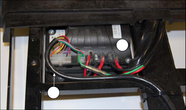
12. Cut any zip ties securing the main harness. Figure 37. Control Panel Removal
13. Fish the main harness up through the opening in the tiller, and then
up through the tiller to the console to remove. See figure 38.
14. Fish the new main harness through the tiller.
15. Connect the new main harness to the control panel and the controller.
16. Reassemble the (2) halves of the control panel.
17. Reinstall the control panel shroud.
18. Reinstall the front shroud.
19. Reinstall the floor shroud.
20. Reinstall the (2) gray textured floor inserts.
21. Reinstall the battery pack.
22. Reinstall the seat.
Figure 38. Tiller Opening
Opening
Tiller
Console
Front
Shroud
Buzzaround XL_SG_REVA
23
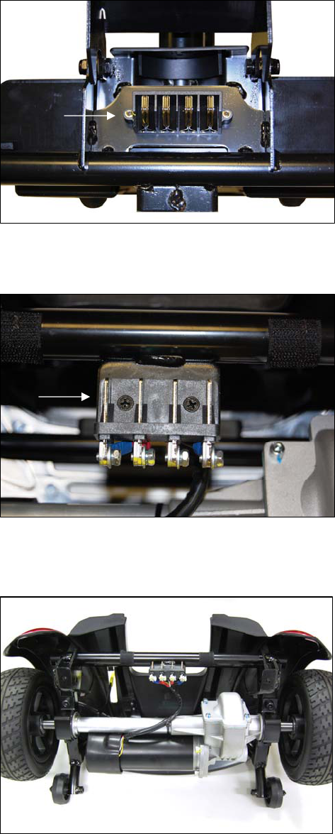
MOTOR/BRAKE ASSEMBLY REPLACEMENT
Tools needed: Phillips screwdriver, 5mm Allen wrench, cutters
1. Place the freewheel lever in the engaged position.
2. Remove the key from the key switch.
3. Remove the seat.
4. Remove the battery pack.
5. Separate the front and rear frames.
6. Remove the rear color panels by lifting them up.
7. Remove the rear shroud.
8. Remove the (2) Phillips head screws connecting the
rear intermediate connector to the frame.
9. Cut the zip tie securing the wire harness to the transaxle.
10. Remove the (4) bolts that fasten the motor/brake to
the transaxle. See figure 39.
11. Remove the motor/brake assembly.
Make sure you retain the motor key.
12. Align and place the new motor/brake onto the transaxle.
13. Fasten the new motor/brake onto the transaxle with the
four screws removed in step 9.
14. Install the rear shroud.
15. Reinstall the color panels.
16. Connect the front and rear frames. Figure 39. Motor/Brake Removal
17. Reinstall the battery pack.
FRONT INTERMEDIATE HARNESS REPLACEMENT
Tools needed: Phillips screwdriver, 7mm wrench
Figure 40. Connector (Front View)
1. Place the freewheel lever in the engaged position.
2. Remove the key from the key switch.
3. Remove the seat.
4. Remove the battery pack.
5. Separate the front and rear frames.
6. Remove the (2) gray textured floor inserts by lifting them up from each side of the floor shroud.
7. Remove the floor shroud by removing the (4) screws securing it to the frame.
8. Remove the battery tray by removing the (2) screws securing it to the frame.
Note: This will allow access to the hardware/connections at the rear of the connector.
9. Remove the (2) screws from (back side of connector) securing the connector to the frame.
Please note the placement of all wiring prior to removal.
Brake
BoltsBolts
Moto
r
Buzzaround XL_SG_REVA
24
At this time the entire harness can be removed by simply disconnecting the red and black motor wires
and the 2-pin red/black connector from the controller.
At this time to replace only the connector or harness separately, continue to step 10.
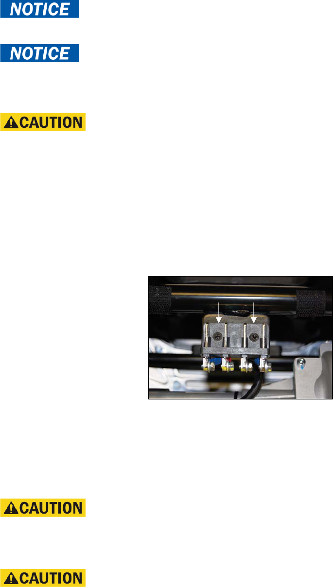
10. Remove the (4) bolts securing the wires to the back of the connector.
11. Install either the new connector or the new harness/connector.
Wire placement is critical. If you are unsure of the placement, refer to the wiring diagram on
page 10.
17. Reinstall the battery tray.
18. Reinstall the floor shroud.
19. Reinstall the two gray textured floor inserts.
20. Reconnect the front and rear frames.
22. Reinstall the battery pack.
23. Reinstall the seat.
REAR INTERMEDIATE CONNECTOR REPLACEMENT
Tools needed: Phillips screwdriver, 7mm wrench
Figure 41. Connector (Front View)
1. Place the freewheel lever in the engaged position.
2. Remove the key from the key switch.
3. Remove the seat.
4. Remove the battery pack.
5. Separate the front and rear frames.
Please note the placement of all wiring prior to removal.
6. Remove the (4) bolts connecting the harness to the connector.
7. Remove the (2) screws securing the connector to the frame.
8. Install the new connector.
Wire placement is critical. If you are unsure of the placement, refer to the wiring diagram on
page 10.
9. Reconnect the harness to the connector.
10. Reconnect the front and rear frames.
11. Reinstall the battery pack.
12. Reinstall the seat.
Buzzaround XL_SG_REVA
25
POWER HARNESS REPLACEMENT
Tools needed: Phillips screwdriver, 7mm wrench
Figure 42. Connector (Top View)
1. Place the freewheel lever in the engaged position.
2. Remove the key from the key switch.
3. Remove the seat.
4. Remove the battery pack.
5. Separate the front and rear frames.
6. Remove the (2) gray textured floor inserts by lifting them up from each side of the floor shroud.
7. Remove the floor shroud by removing the (4) screws securing it to the frame.
8. Remove the battery tray by removing the (2) screws securing it to the frame.
9. Remove the (2) screws securing the connector to the battery tray.
Please note the placement of all wiring prior to removal.
At this time the entire harness can be removed by simply disconnecting the red and black battery wires
and the green wire from the controller.
At this time to replace only the connector or harness separately, continue to step 10.
10. Remove the (4) bolts securing the wires to the back of the connector.
11. Install either the new connector or the new harness/connector.
Wire placement is critical. If you are unsure of the placement, refer to the wiring diagram on
page 10.
17. Reinstall the battery tray.
18. Reinstall the floor shroud.
19. Reinstall the two gray textured floor inserts.
20. Reconnect the front and rear frames.
22. Reinstall the battery pack.
23. Reinstall the seat.
Buzzaround XL_SG_REVA
26
APPENDIX A - HOW TO USE A VOLTMETER
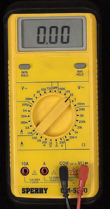
Step 1
Plug the probes into the meter. Red goes to the positive (+) and black to the negative (-).
Step 2
Turn the selector dial or switch to the type of measurement you want. To measure direct current - a battery, for
example - use DCV. To measure alternating current, such as a wall outlet, use ACV.
Step 3
Choose the range setting. The dial may have options from 5 to 1000 on the DCV side and 10 to 1000 on the ACV
side. The setting should be the top end of the voltage you are reading. Not all voltmeters have this setting.
Step 4
Turn the meter on.
Step 5
Hold the probes by the insulated handles and touch the red probe to the positive side of a DC circuit or either side
of an AC circuit. Touch the other side with the black probe.
Step 6
Read the digital display or analog dial.
Figure 43. Multimeter (Set to DC Volts)
Buzzaround XL_SG_REVA
27
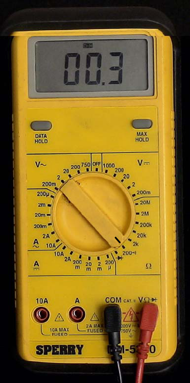
APPENDIX B - HOW TO USE AN OHM METER
Ohm’s law breaks down into the basic equation: Voltage = Current x Resistance. Current is generally measured
in amps, and resistance in ohms. Testing the resistance on an electrical circuit in your home or car can help you
diagnose problems with that circuit. You can use a simple ohmmeter for this task, but most professionals now use
the ohmmeter function of a multimeter (also called multitester or VOM, for volt/ohmmeter). Read on for instructions
on how to use an ohmmeter and test for resistance.
Ohmmeter or Multimeter (Volt/ohmmeter)
Circuit to test (with all power OFF)
Service manual
Step 1
Disconnect completely and/or turn OFF all power to the
circuit you are testing. You must have a completely dead
wire or circuit in order to ensure accuracy in measurement,
as well as your own safety. Your ohmmeter will supply the
voltage and current for your circuit so NO other power is
necessary. Testing a powered circuit can “cause damage to
the meter, circuit, and *you*.”
Step 2
Connect testing wires to the ohmmeter. The black wire
goes to the ground (common) outlet, the red wire to the
volt/ohms outlet.
Step 3
Consult a service manual for the normal range of
resistance for the circuit you are testing.
Step 4
Set the dial to the “ohms” setting with a multimeter. On an
individual ohmmeter, you may have to set a range for the
readings, in ohms, kilohms or megohms. Use the range you
located in your service manual to set the dial.
Figure 44. Multimeter (Set to Ohms)

Buzzaround XL_SG_REVA
28

Buzzaround XL_SG_REVA
29
BUZZAROUND XL_SERVMAN_REVA_110915
Golden Technologies
401 Bridge Street
Old Forge, PA 18518
www.goldentech.com
Model GB147S Model GB117S
